






Electrical shop drawings
Get Every Conduit Right Before Crews Install It
Conduit installed from unclear drawings gets pulled and rerun. Our coordinated, code-ready shop drawings are checked sheet by sheet, so crews install it once.
See What Electrical Rework Costs You- Clearances checkedElectrical rooms that pass inspection.
- Sleeves set before the pourNo core drilling after concrete.
- Coordinated with every tradeClashes cleared before installation.
- Checked before releaseSenior review on every set.
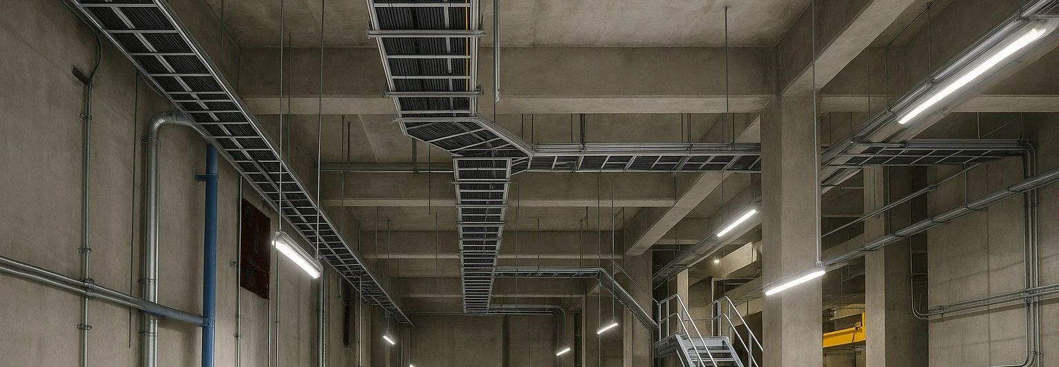 Electrical service levels
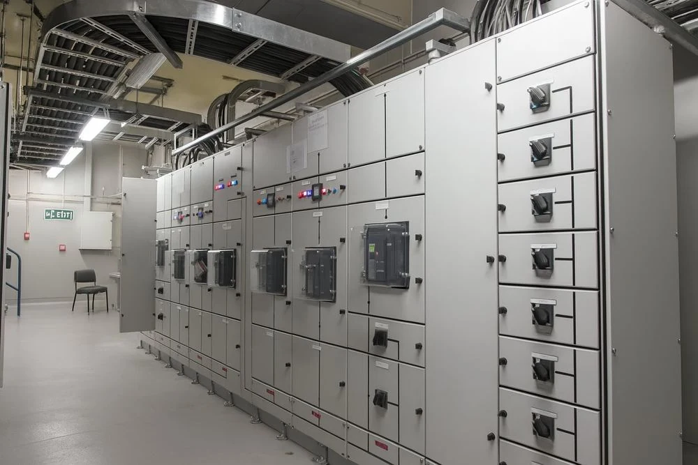 Distribution hall
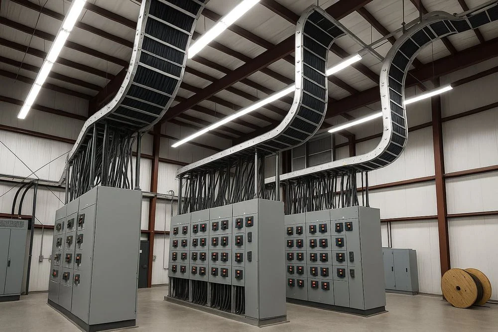 Tray to switchgear
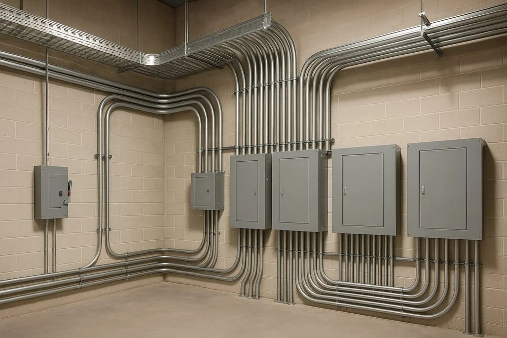 Conduit routing
- 20+Years’ experience
- 1,500+Projects supported
- 350+Engineering professionals
- 80%Repeat clients
Where margin leaks
Every Rerun Conduit Costs Your Margin
Electrical runs through every floor. Each drawing error means rerun conduit or a failed inspection.
Field Clashes
- Where margin leaks
- Conduit and cable tray hit ducts, pipes and structure, and crews reroute in the field.
- What we fix
- Shop drawings built from a coordinated model, with clashes cleared before installation.
Clearance Failures
- Where margin leaks
- Panels and switchgear without code working space fail inspection and have to move.
- What we fix
- Electrical rooms laid out with code clearances checked on every sheet, so gear stays put.
Missed Sleeves
- Where margin leaks
- Penetrations left off the drawings mean core drilling and engineer reviews after the pour.
- What we fix
- Every sleeve and opening dimensioned and issued before concrete is poured.
Slow Submittal Approvals
- Where margin leaks
- Incomplete or non-compliant drawings are rejected, and installation waits.
- What we fix
- Submittal-ready sets prepared to the NEC and your standards, so approvals come first time.
What we deliver
Electrical Drawings Your Crews Can Install From
Electrical Shop Drawings
Installation drawings for power, lighting, low voltage and fire alarm.
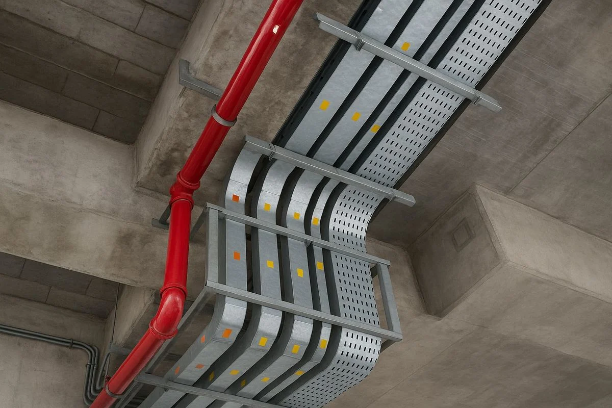
Conduit and Cable Tray Layouts
Routing, bends, supports and elevations set out clearly.
Electrical Room Layouts
Switchgear, panels and transformers with clearances checked.
Sleeve and Penetration Drawings
Every opening set out before the pour.
Panel Schedules and Riser Diagrams
Circuits and distribution shown clearly, floor by floor.
As-Built Drawings
A verified record of installed electrical systems.
- We work in
- Autodesk Revit
- AutoCAD MEP
- Navisworks
- Your templates and standards
- Works with
- Electrical BIM
- MEP BIM
- Mechanical Shop Drawings
Level of development
More Detail, Less Electrical Rework
Thin shop drawings get rejected or installed twice. Drawn too early, they chase routes that will change.
- Stage
- LOD 100Concept
- LOD 200Schematic Design
- LOD 300Coordinated Design
- LOD 350/400Shop Drawings
- LOD 500As-Built
Cost to change a decision
Low
Moderate
High
Very high
Highest
Confidence in the model
Indicative
Approximate
Coordinated
Build-ready
Verified
Decide early, while change is cheap. Build from a model you can trust.
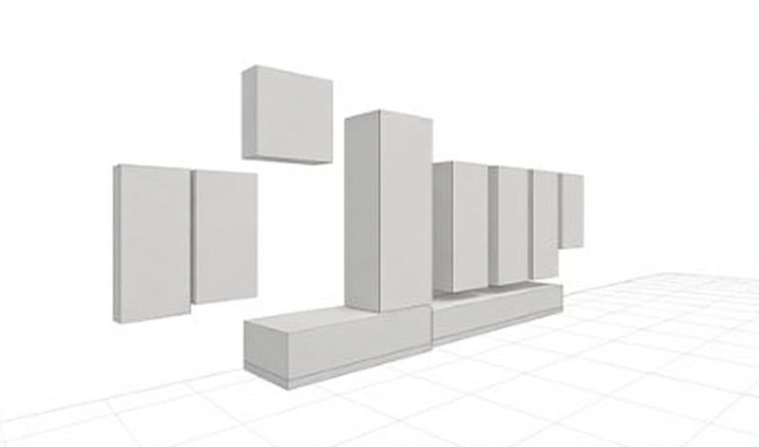
LOD 100 Concept
Early Visionowners & electrical engineers
Check space and load early, before routing is committed.
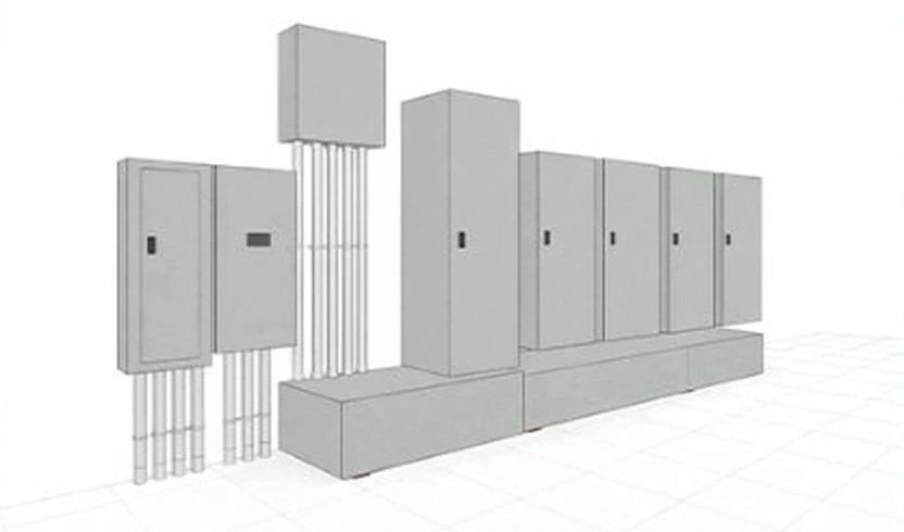
LOD 200 Schematic Design
Early Routingelectrical engineers & contractors
Price the main routes realistically before later changes add cost.
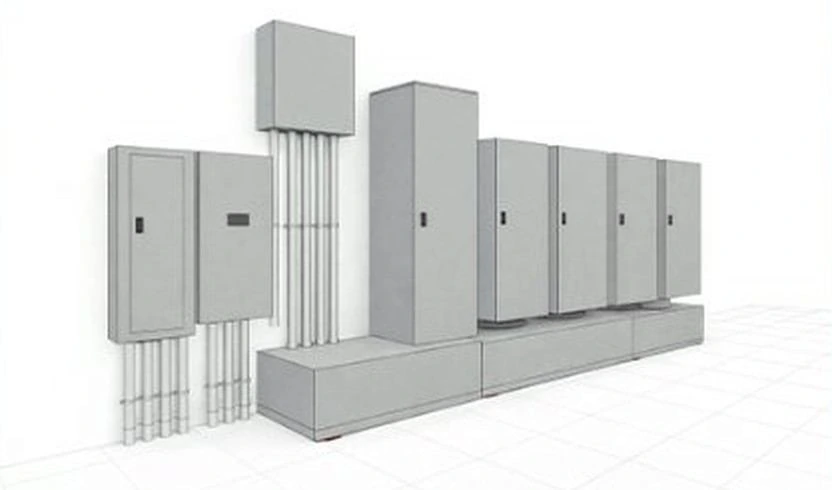
LOD 300 Coordinated Design
Accurate & CoordinatedMEP coordinators & general contractors
Resolve clashes and clearances before shop drawings are drawn.
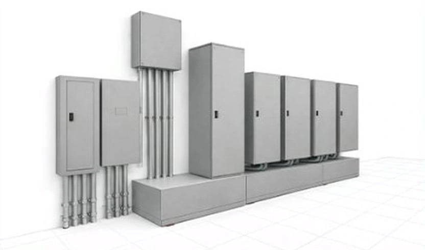
LOD 350/400 Shop Drawings
Installation-ReadyWhere most margin is protected
Typical for shop drawings
electrical contractors & installers
Get shop drawings approved and install the work right the first time.
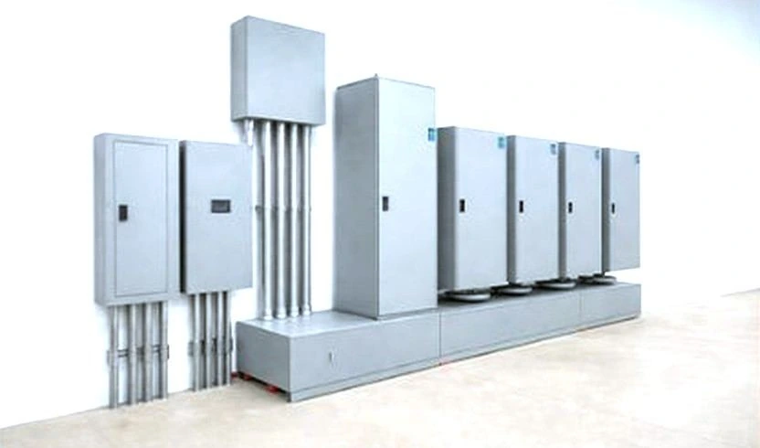
LOD 500 As-Built
Record Drawingsowners & facility teams
Hand over a verified record for safe future electrical changes.
Not sure which LOD your program needs?
A senior engineer will tell you, and what each choice costs, in your Margin Assessment.
How it works
From Design to Installation
Shop drawings are coordinated and checked before crews pull a single wire.
- 01
Share Your Documents
Send drawings, models and specs. We confirm scope, deliverables and dates in writing.
- 02
Coordinate and Detail
Routing, sleeves and rooms are cleared with every trade before the drawings are released.
- 03
Check and Submit
Senior review to the NEC (NFPA 70) and AS/NZS 3000 before any model is released.
- 04
Support Through Install
Fast RFI answers and revisions on site, through installation, so crews avoid costly rework.
How Much Margin Is Electrical Rework Quietly Costing You?
A two-minute Margin Assessment shows where your programs leak, in dollars, and what electrical work installed right the first time could save.
What clients ask first
Electrical Shop Drawings: Common Questions
Straight answers from our engineering team. If your question isn’t here, ask us directly.
What do your electrical shop drawings include?
Installation drawings for electrical systems: conduit and cable tray routing, equipment locations, panel schedules, clearances and connections.
Which codes do you follow, and who is responsible for the design?
The NEC (NFPA 70) for US projects and AS/NZS 3000 for Australian projects. Design responsibility stays with your engineer of record, who reviews and seals the work. Bimgraphix does not stamp drawings; we answer for every sheet matching your design inputs, and any gap is raised as an RFI, never guessed.
How do you make sure drawings pass inspection?
Working clearances, tray fill and routing are checked in a coordinated model, then every sheet is senior-reviewed before submittal.
How fast can you deliver, and how is it priced?
We quote per floor or per package and confirm the delivery schedule in writing before work begins, so dates and costs are known on day one. Work is released floor by floor or by system, so your team can start early. You can begin with one floor and judge the quality before committing the full program.
Is our project information kept confidential?
Yes. We work under your NDA from the first file. Everything we produce, including models and drawings, belongs to you, is shared only through Autodesk Construction Cloud, Procore or a secure link, and is seen only by the team assigned to your project.
Start a conversation
Built for Programs Where Precision Is Never Optional.
For over 20 years, one standard has guided every model, drawing and component. Let’s talk about where your programs are losing margin.
Or write to info@bimgraphix.com
- Response within one business day
- Reviewed by a senior engineer
- Confidential